Category Archives: From the Shop

Robots, with Frickin Lasers – Early tests

I can’t claim these are the best work I’ve done.  There’s still a lot to learn.

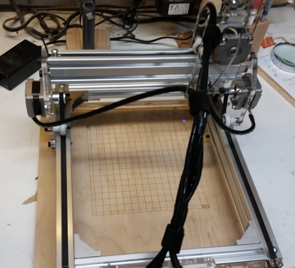
Creating content from scratch is pretty easy using Inkscape and the laserengraver extension from this instructables post. I should also note that I’m using a laptop running ubuntu and Universal G-code Sender to control the machine.

So, Like I said, straight vector based graphics are pretty easy to manage and come out quite well.  But an awful lof of content you might want to play with are raster based.  I’ve experimented with 2 methods of generating gcode from raster images.

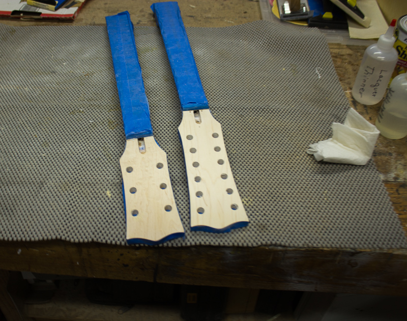
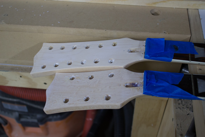
The first is to use Gimp to edit the file and adjust the color levels to try and get an image that has only black and white in it.  This can be easier said than done, and may require some manual clean up work.  Once doing that, you can transfer the bitmap into Inkscape and use the ‘Trace Bitmap’ tool to convert that into a series of paths (? still learning inkscape and its terminology).  That method can require quite a bit of clean up of the paths, depending on how good of a job at converting to black and white you did.

These two are examples of that method.  The one on the left I might need to decrease the speed of the laser to burn a little deeper.  The one on the right, you can see some speckles in it that I later cleaned up by removing the paths that made up those dots.

rnr_rpr20150815_151957

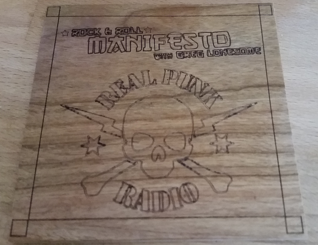
Another method is to use LaserEtch by JTech Photonics.  You still need to convert an image to BW, and do some clean up.  It then generates G-code that will etch the image by going back and forth and turning the laser on and off.  This method will be very useful for creating PCB’s, but it’s can also be used to burn an image that you might not want to turn into vectors.  Here’s a pic of a logo I threw together quickly for a great radio show you can hear on Thursday nights.  It’s Zorch Radio on Real Punk Radio.  Hell, Tune in to the entire Wrecking pit and listen to Gone Mental at 6:00pm and Zorch Radio at 7:00 till 10:00pm.

I think with a little manual edting of the file I can clear this up quite a bit.  Took me 5 minutes to convert the image, and rendering probably took around 45 minutes for a 95mm x 20mm image.

zorchlasered

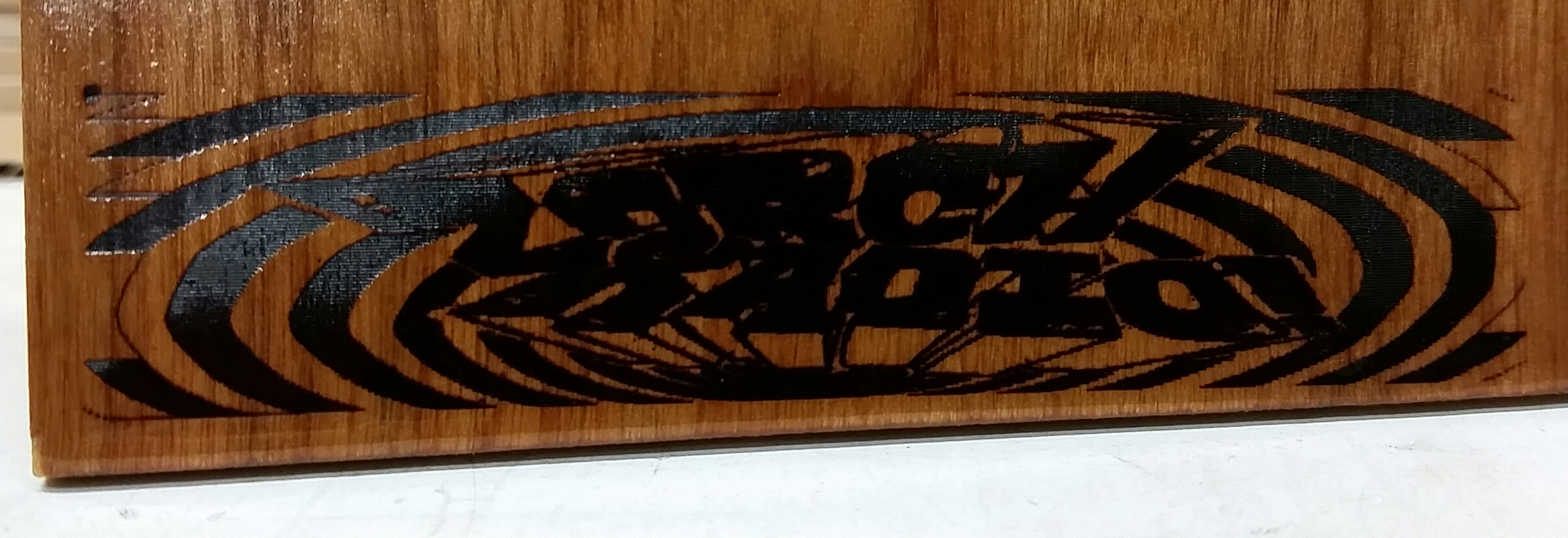
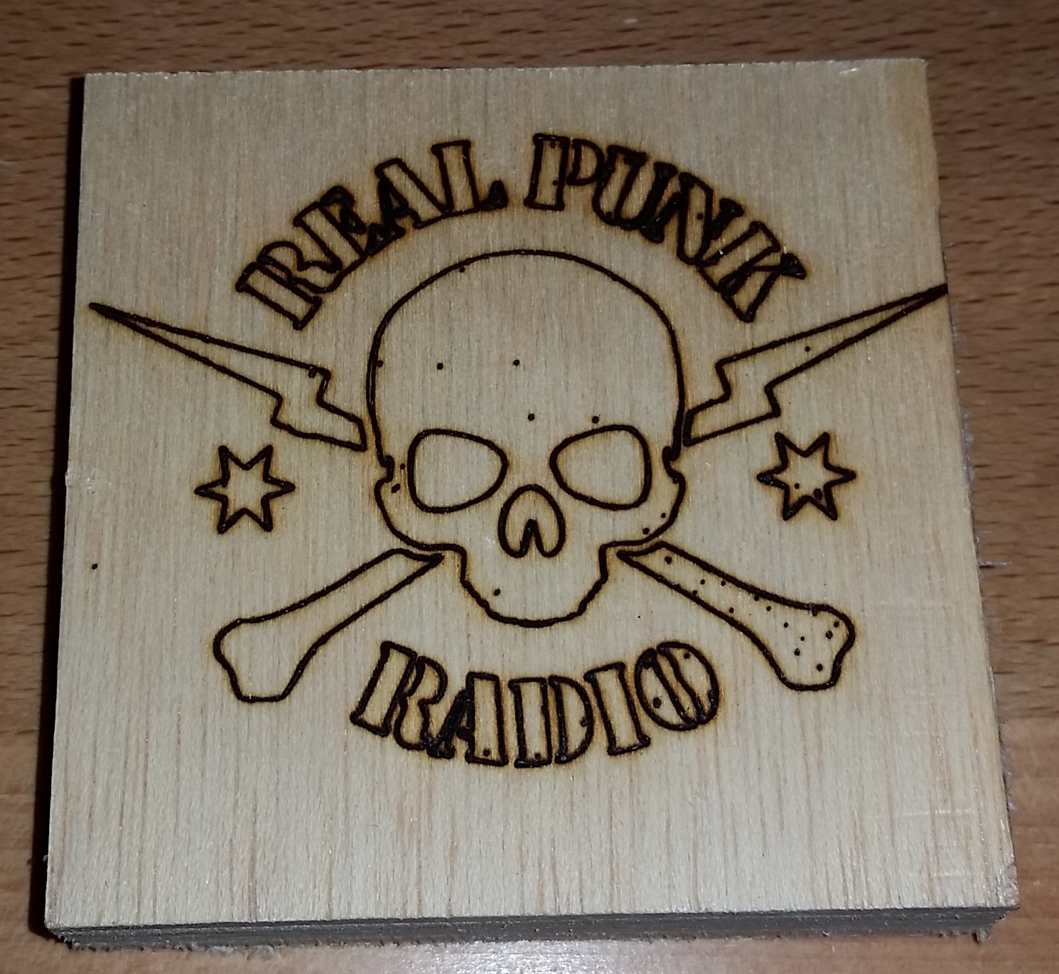
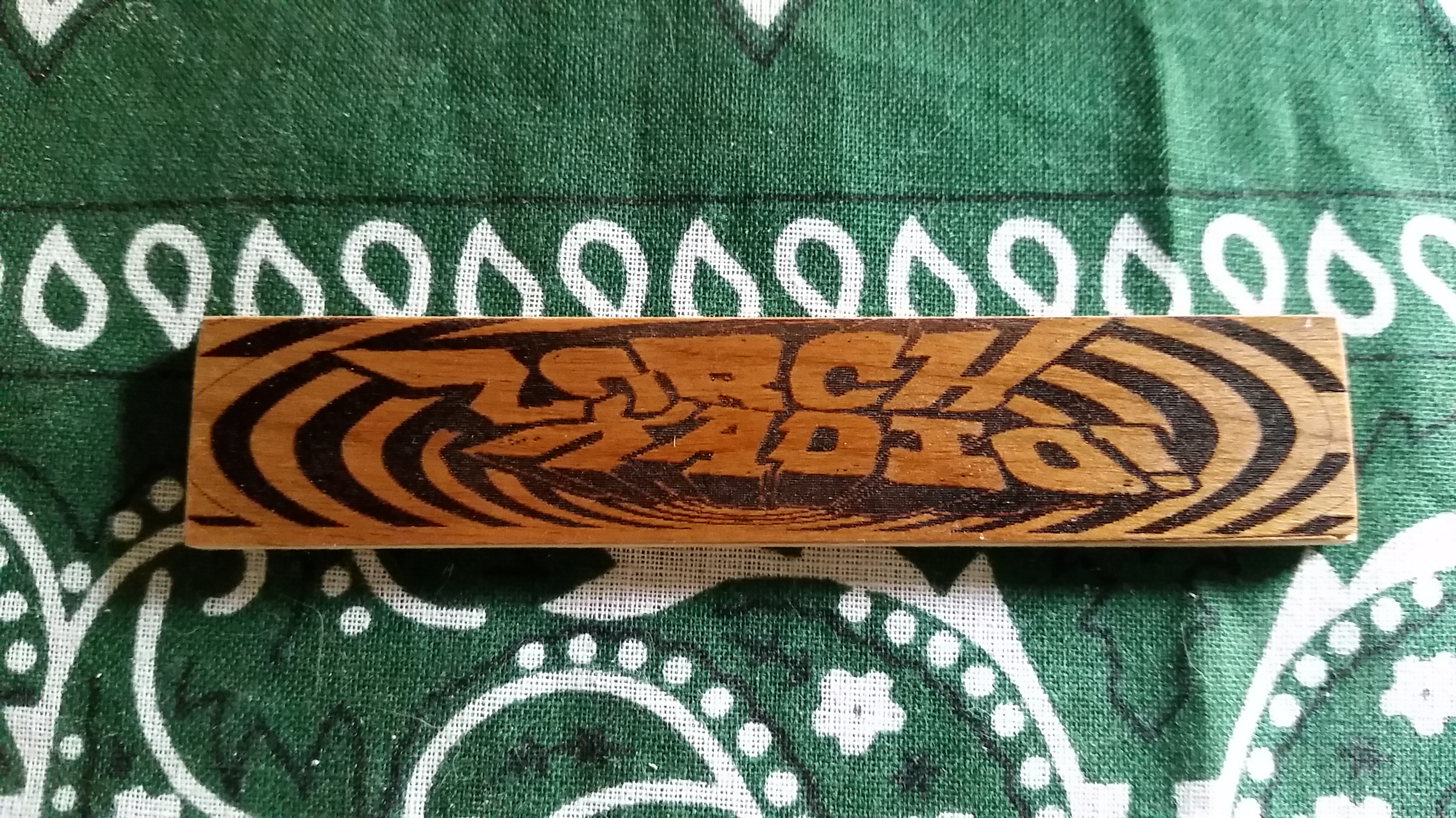
Edit: Inverted the black and white and did a little cleanup to make the letters more separated.  Turned out much better.

zorchburned

Robots, with Frickin Lasers – GRBL Settings

While setting up my NEJE 500mw Desktop violet laser engraver, I found there was absolutely no documentation.  It came with a version of grbl on it, but I updated it to the latest Grbl 0.9j.

These settings are working pretty well for me.  I’ve tweaked the dir port invert mask to make the origin (0,0) take place when the gantry is closes to the circuit board.

Grbl 0.9j ['$' for help]
>>> $$
$0=100 (step pulse, usec)
$1=25 (step idle delay, msec)
$2=0 (step port invert mask:00000000)
$3=2 (dir port invert mask:00000010)
$4=0 (step enable invert, bool)
$5=0 (limit pins invert, bool)
$6=0 (probe pin invert, bool)
$10=3 (status report mask:00000011)
$11=0.010 (junction deviation, mm)
$12=0.002 (arc tolerance, mm)
$13=0 (report inches, bool)
$20=0 (soft limits, bool)
$21=0 (hard limits, bool)
$22=0 (homing cycle, bool)
$23=0 (homing dir invert mask:00000000)
$24=250.000 (homing feed, mm/min)
$25=250.000 (homing seek, mm/min)
$26=250 (homing debounce, msec)
$27=10.000 (homing pull-off, mm)
$100=80.000 (x, step/mm)
$101=80.000 (y, step/mm)
$102=80.000 (z, step/mm)
$110=750.000 (x max rate, mm/min)
$111=750.000 (y max rate, mm/min)
$112=500.000 (z max rate, mm/min)
$120=1000.000 (x accel, mm/sec^2)
$121=1000.000 (y accel, mm/sec^2)
$122=10.000 (z accel, mm/sec^2)
$130=175.000 (x max travel, mm)
$131=1200.000 (y max travel, mm)
$132=175.000 (z max travel, mm)
ok

Robots, with Frickin Lasers…

Wow, It’s been far too long since I’ve updated the site.  It’s not that I haven’t been doing stuff, I’ve just been bad at documenting them.

Well, the latest project really deserves a post.  For a while now, I’ve been wanting to do 2 things.  1) be able to make my own PCB’s, and 2) get started in using CNC (Computer Numerically Controlled) machines (robots!).

NEJE 500mW Desktop Violet Laser Engraving Machine Printer

So I find one day searching the interwebs there is a method for making PCB (printed circuit boards) that uses a laser.  The basic process is you take a blank copper pcb, paint it with black paint, use the laser to etch off the paint where you don’t want the copper to be, then use acid to remove the copper.  And then I find this little laser kit online.  Not too expensive, so I take a shot on it.

20150812_143756

Shipping from China it took a little while to get here, but it made it. The parts all seemed to be pretty solid and everything was there.  It was basically just a box of parts, with no instructions, no documentation at all.

Assembly was straightforward though and went quickly.

Gotta say I’ve got no complaints.

20150820_143040
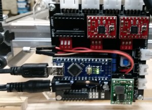
Ok, Maybe one complaint.  At some point during the first day, the laser quit being able to shut off during use.  It appears that the SMD mount transistor on the board that controls the laser went bad.  In my attempt to replace it, I managed to screw up the board a bit, but finally just soldered some jumper wires in place and plugged in a replacement transistor I had laying around.  Bada Bing, Bada boom, I’m back in business.  It looks a little goofy, but it works fine now.

20150820_143032Here it is all together. I printed a little grid on the backing board.  Really quite a lot of fun.

2.25 sq Foot Gardening Separator and watering system

So, The whole square foot gardening method is very popular.  I really like the idea of it and gave it a shot last year.  For whatever reason, We just found the 12″ squares were a little small for our liking.  So we made ours just a little bit bigger, and that’s why it’s called 1.5′ Squared gardening, or 2.25 square.

Anyhow, putting in drip irrigation in these things can be a little challenging, so I thought, why not make the grids do the watering?  So I’ve made some out of PVC tubing and fittings and drilled 1/16″ holes in the tubes. to let the water out.

I’m no hydraulic engineer, but it works pretty good.  With the water running full blast, all the holes have just enough pressure to squirt out a few inches, but not under so much pressure to be damaging.  A minute or two of running does a great job of evenly watering the whole bed right at ground level.

Step 1: Cut the tubes

Cut out 45 sections of 1/2″ PVC tube 14″ long.  Why 14″?  Well It worked out just right in my 4’x8′ raised beds with a little extra room.

Step 2: Mark a Guide Line

Mark a straight line on each of the cut pieces.  We will be using this as a guide when we drill the holes to make sure they are all lined up right.

20140518-IMG_0909

Step 3: Drill baby Drill!

Time to drill some holes.  Here’s where it gets tricky, 18 of these will get holes on only one side, 27 will get holes drilled all the way through.  I made a mark on 18 of them to let me know they should only get drilled on on side.

I used a v-block on my drill press to make sure that I drilled right in the center of the tubes,

So, Go ahead and drill the holes 1/2 through on 18, and all the way through on the remaining 27.  Make sure you keep them separate!


20140518-IMG_0912 20140518-IMG_0911 20140518-IMG_0910

Step 4: Get your parts together

You’ll need 4 1/2″ pvc 90’s, 10 1/2″ pvc crosses, 1 1/2″ slip fit pvc Tees, and 1 1/2″ Tee with a fip fitting on the tee, and slip on the sides.

You’ll definitely want to have gloves on when working with PVC Primer and Cement.  It’s messy stuff, so make sure to do it somewhere you can get messy.

Go ahead and prime all your tube pieces and connectors.

It doesn’t hurt to give everthing a blast with the air hose to get any little bits of plastic that could clog your holes.

20140518-IMG_0916 20140518-IMG_0917 20140518-IMG_0918 20140518-IMG_0919

Step 5: Glue it up.

There’s no way to get around it. This is tedious, and you need to make sure you get it right.  PVC glue is unforgiving after it sets.  Make sure to put plenty of glue on both sides of the piece to make sure you have time to twist the tubes so the holes line up the right way.

Also make sure that you put the parts together right.  The pieces with the holes on only one side go around the outside with the holes pointing in..

One tip is to use a flat surface when starting to make sure you get the fittings lined up parallel to each other.

I don’t have any other tips other than take your time, think about what type of tube goes where and make sure you get the holes pointing the right way.

20140518-IMG_0922 20140518-IMG_0923 20140518-IMG_0924 20140518-IMG_0925

Step 6: Protect it!

I like to put a coat of brown spray paint on it to protect the pvc from the sun and to make it blend in to the garden a bit better.

20140518-IMG_0926 20140519-IMG_0927

And that’s about it.

If you made it this far, here’s a little video showing how it works. Please ignore the artichokes, they were badly mistreated by me and should have been in the ground a while ago.

Fermentation Chamber

Had a request for some details on my fermentation chamber.

It’s a pretty simple plywood box on a stand and casters, lined with styrofoam insulation board.

I modified the cheapest, smallest window ac unit I could find to move the bulb thermostat from inside the unit, to outside underneath the AC.  Since our nights can be cool here, I also put the bulb inside a tin can with a 7w nightlight to make sure that when the external controller tells it to turn on, it will turn on.

Currently using an stc-1000 temp controller to control both the AC unit and a small heater.  Oddly enough, over the spring, both of those have come on at some point or other.  If the beer gets too cool, fermentation can slow down or stop, so it’s important to maintain an even temp.

Currently, I’m working on adding a Pinoccio based fermentation controller that will allow me to put the data and control of the unit up on the web.

20140514-IMG_0861 20140514-IMG_0860 20140514-IMG_0859

Priming Guitar

Looks like I have more sanding to do.  I had put a couple of coats of sealer on and sanded it all down, but not good enough.

Once this dries, I’ll pull out the 320 and give it another sanding.  No need to go down to bare wood, but I will sand it and re-prime it until all the little defects disappear, before putting the color coats on.

20140426-IMG_0760 20140426-IMG_0770

Double Neck – Paint Prep

Painting is hard for me.  I like instant gratification.  It takes everything I have to just not grab the can of paint and start spraying on on the bare wood.

But what I’ve read, and started to learn and get stuck into my thick head is that the quality of the finished product really relys on the prep work you do before you ever take the cap of the can of paint.

So here are the parts with all the old finish stripped and cleaned off.  I’ve sanded them up to 320 grit and have wiped them off with lacquer thinner and naptha.  Since I literally hosed the body off, I’m going to let every thing dry out for a little while before  I move to the next step.

The next step will be to put a seal coat (or 2) of lacquer on the parts, let that dry, and sand those back on up to 320 again, just to make sure the wood is sealed and properly prepared for painting.

This is killing me. It’s going to take days and I’d much rather be putting the electronics together.

20140418-IMG_0705 20140418-IMG_0703

Double Neck Guitar Project

So a buddy of mine got this guitar for cheap off of ebay.  It’s an inexpensive chinese guitar, probably a kit put together by somebody here in the states.  The hardware on it is ‘ok’, but the pickups really needed replacing.  So I bought it off him and we came up with a plan for rewiring it using some new dragonfire screamer pickups and push pull pots so I could do the humbucker coil tap mod.

20140410-IMG_0656

I’ll be doing away with the tone knobs, and basically each knob will control one pickup.  The switches will still do the front/both/bridge and top/both/bottom neck selections.

Since I was going to do that much work, I decided I might as well just go full bore and repaint it as well.  Not a fan of the plain white paint job on it.

Here’s a couple of pics I took before I remove everything from the guitar.

20140417-IMG_0674 20140417-IMG_0671

And here we go, stripping the paint off the body and the headstocks.

20140417-IMG_0687 20140417-IMG_0686

Stay tuned, More to come this weekend.